The basic knowledge of optical fiber is detailed
TIME:2023-09-30
Optical fiber construction
Optical fibers for communication are made of glass that transmits light signals through total internal reflection. The standard diameter of the glass fiber is 125 microns (0.125 mm) and the surface is covered with a 250 micron or 900 micron diameter resin protective coating. The central part of the glass fiber that transmits light is called the "core", and the cladding around it has a lower refractive index than the core, thus limiting the loss of light.
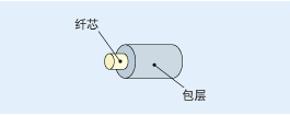
Quartz glass is so fragile that it is coated with a protective coating. There are usually three typical fiber coating layers.
Coating the fiber once
Fiber coated with UV-curable acrylic resin with a diameter of 0.25 mm. Its diameter is very small, increasing the density of the fiber that can be accommodated in the cable, and its use is very common.
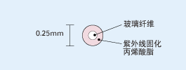
The optical fiber is coated twice
Also known as tightly packed buffer fiber or semi-tightly packed buffer fiber. The fiber is coated with thermoplastic resin with a diameter of 0.9 mm. Compared with 0.25mm fiber, it has the advantage of being stronger and easier to operate. It is widely used in local area network wiring and optical fiber cable with a small number of optical fibers.
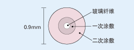
Ribbon fiber
Ribbon fiber improves the efficiency of connector assembly and is conducive to multi-core fusion, thus improving the working efficiency.
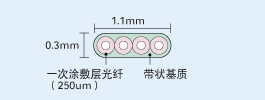
The ribbon fiber consists of 4, 8, or 12 fibers of different colors, with a maximum number of 1,000 core fibers. The fiber is coated with a UV-curable acrylic material that can be easily removed using standard fiber strippers for multi-core fusion or single fiber removal. Using multi-core fusion splicing machine, the ribbon fiber can be fused at one time, and it can be easily identified in the cable with a large number of optical fibers.
Type of optical fiber
The following is a description of the most commonly used types of communication fiber.
MMF (Multi-Mode Fiber)
- OM1 Fiber or multimode fiber (62.5/125)
- OM2/OM3 Fiber (G.651 fiber or multi-mode fiber (50/125))
SMF (Single Mode Fiber)
- G.652 (Dispersion-unshifted single-mode fiber)
- G.653 (Dispersion-shifted fiber)
- G.654 (Cut-off wavelength Shift fiber)
- G.655 (non-zero dispersion shifted fiber)
- G.656 (Low slope non-zero dispersion shifted fiber)
- G.657 (Bending fiber)
As long as the optical budget allows, technically, any suitable fiber can be used in FTTx technology, but the most commonly used fiber FTTx technology is G.652 and G.657.
G.651 (Multimode Fiber)
G.651 is mainly used in local area networks and is not suitable for long-distance transmission, but in the range of 300 to 500 meters, G.651 is a lower cost multi-mode transmission fiber.
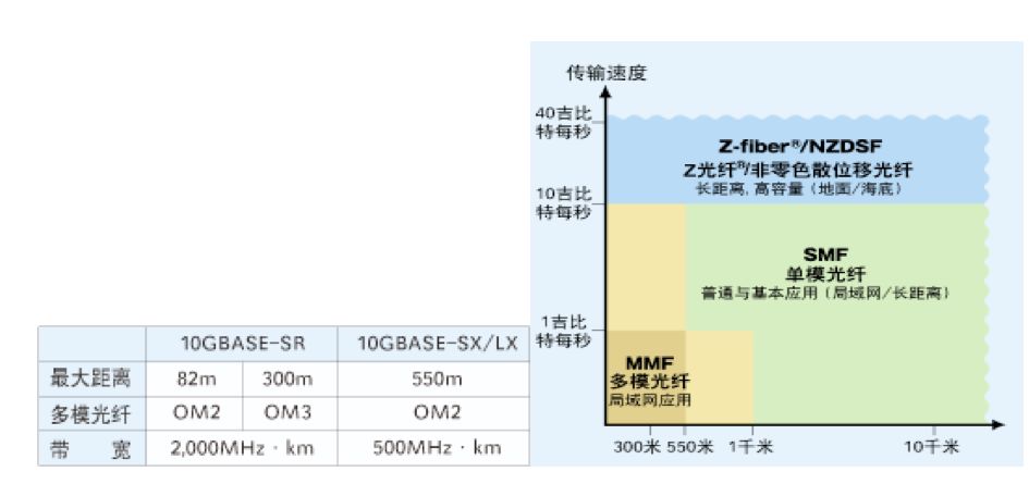
ITU-T G.651 fiber is OM2/OM3 fiber or multimode fiber (50/125). The ITU-T recommendation does not include OM1 fiber or multimode light (62.5/125).
The reflectivity of the multimode fiber (50/125) core gradually changes from the center to the cladding, so that multiple optical transmission can be carried out at the same speed.

G.652 Optical Fiber (Dispersion-unshifted Single-mode Fiber)
The most common single-mode fiber in the world. The dispersion that deforms the signal at wavelengths around 1,310nm can be minimized. You can use the 1550nm wavelength operating window for short distance transmission or with dispersion-compensated fibers or with modules.
G.652A/B is a basic single-mode fiber, and G.652C/D is a low-water peak single-mode fiber
G.653 (Dispersion-shifted Fiber)
This fiber minimizes dispersion at wavelengths around 1,550nm, thereby minimizing light loss.
G.654 (Cut-off wavelength Shift Fiber)
G.654 is officially known as cutoff wavelength shift fiber, but is commonly referred to as low attenuation fiber. The low attenuation characteristics of the G.654 fiber make it mainly used in underwater or surface long-distance transmission, such as 400 km without transponder lines.
G.655 (Non-zero dispersion shifted Fiber)
The G.653 fiber has zero dispersion at 1,550nm, while the G.655 fiber has concentrated positive or negative dispersion, which reduces the adverse effects of nonlinear phenomena that interfere with adjacent wavelengths in the DWDM system.
The first generation of non-zero dispersion-shifted fibers, such as PureMetro® fibers, have the advantage of dispersion-per-kilometer at or below 5ps/nm, making dispersion compensation easier. Second-generation non-zero dispersion-shifted fibers, such as PureGuide®, achieve dispersion of around 10ps/nm per kilometer, doubling the capacity of DWDM systems.
G.656 Fiber (Low-slope non-zero dispersion shift fiber)
A type of non-zero dispersion-shifted fiber that has strict requirements for the speed of dispersion, ensuring transmission performance over a larger wavelength range in DWDM systems.
G.657 (Bending resistant Fiber)
The latest member of the ITU-T optical fiber family. New products based on FTTx technology requirements and assembly applications.
The G.657A fiber is compatible with the G.652 fiber, and the G.657B fiber does not require connection compatibility with traditional single-mode fibers.
Classification of fiber optic wiring technology
Optical fiber wiring technology can be divided into fusion, mechanical splice and connector wiring. Fusing and mechanical splicing are permanent connections, and connector connections can be disassembled repeatedly. Optical connector wiring is mainly used for connecting points that must be switched during the use and maintenance of optical services. Permanent wiring is mainly used in other places.
Principle of loss in optical fiber wiring
Optical fiber cables must be connected so that the part of the fiber core through which the light passes is opposed and correctly positioned.
The connection loss of optical fiber is mainly caused by the following reasons.
(1) Axis offset
The optical axis deviation between the connecting optical fibers will cause the connection loss. In the case of a common single-mode fiber, the connection loss is approximately the square of the axis offset multiplied by a value of 0.2. (For example, when the light source wavelength is 1310nm and the axis offset is 1μm, the wiring loss is about 0.2dB)

(2) Angular deviation
The angular offset between the optical axes connecting the fiber causes the connection loss. For example, if the section Angle cut by the optical fiber cutting knife before fusion becomes larger, the optical fiber will be connected in a inclined state, so you must pay attention to it.

(3) Gaps
The gap between the optical fiber end faces will cause the connection loss. For example, if the ends of the optical fiber connected by mechanical splicing are not properly fitted, it will cause wiring losses.

(4) Reflection
When there is a gap in the end face of the fiber, due to the difference in refractive index of the fiber and the air, the connection loss will be caused by the maximum 0.6dB reflection. And, in order to prevent light interruption, it is important to clean the fiber end face on the optical connector. However, there will be waste in the optical connector end clamp outside the optical fiber end face, so it is important to clean all the optical connector end faces.
Types and principles of fusion
Fusion is a wiring technology that uses the heat generated by the discharge between the electrode rods to melt the optical fiber into a whole. The fusion mode is divided into the following two categories.
(1) Fiber core tuning mode
This is a fusion mode in which the core wires of the optical fiber are observed under a microscope, the central axes of the core wires are aligned through image processing, and then discharge is performed. Positioning is done from both directions using a fusion machine equipped with a two-way viewing camera.
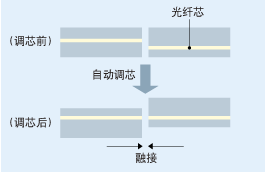
(2) Fixed V-groove core adjustment mode
This is a high-precision V-shaped slot arrangement of fiber, using the surface tension of melting fiber when the core effect of outer diameter core adjustment. Recently, due to the development of manufacturing technology, the dimensional accuracy of the optical fiber core position has been improved, so that low loss wiring can be achieved. This method is mainly used for multi-core one-time wiring.
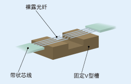
Precautions for fusion operation
This is a high-precision V-shaped slot arrangement of fiber, using the surface tension of melting fiber when the core effect of outer diameter core adjustment. Recently, due to the development of manufacturing technology, the dimensional accuracy of the optical fiber core position has been improved, so that low loss wiring can be achieved. This method is mainly used for multi-core one-time wiring.
① Insert the optical fiber protection tube
Optical fiber protection tubes are used to protect optical fibers exposed at connection points. Since the protective sleeve cannot be inserted, do not forget to insert it.
② Remove the core coating layer
Because the glass part of the fiber is to be exposed, the coating layer is removed with stripping pliers.
(Note) Since coating waste will remain on the stripper after coating removal, remove coating waste and clean the blade.
(Note) When removing the coating layer of the strip core wire, use a heated stripping pliers. To safely remove, heat the coat for about 5 seconds before removing the coat.
③ Clean optical fibers
After removing the coating, clean the glass part with ethanol.
(Note) If there is residual coating waste, the axis may be offset during fusion, and the wiring loss will increase, so please clean carefully.
(Note) In the case of multi-core optical fibers, the front end of the optical fiber will be stuck together due to alcohol, which may cause poor cutting when cutting the optical fiber, so please use your fingers to pop the front end of the optical fiber.
④ Cut the optical fiber
Cut optical fibers by following the steps for cutting optical fibers.
(Note) The cutting will determine the loss characteristics of the fusion. In order to reduce poor cutting, clean the optical fiber holding part and cutting edge of the optical fiber cutting knife.
(Note) Please be careful not to bump or touch the cut fiber front end. Otherwise, the cable connection may be faulty.
(Note) Please be careful not to let the optical fiber scrap scattered everywhere.
⑤ Fuse
Perform the fusion operation according to the operation procedure of the fusion machine.
(Note) If there is garbage on the V-groove and fixture of the fusion machine, it will cause abnormal loss due to shaft deviation, so please fully clean.
(Note) If the bidirectional observation and check function is available before wiring, the abnormal cutting state can be detected before wiring.
(Note) When the optical fiber is bent, gently straighten it with your fingers and bend it downward.
⑥ The fusion part is reinforced
The optical fiber protection sleeve is put on the optical fiber fusion section, and the core wire is reinforced on the heating machine.
(Note) When moving the core wire, avoid bending or twisting the optical fiber. Otherwise, the cable will be damaged and broken.
(Note) Ensure that the center of the optical fiber protection sleeve is consistent with that of the cable connector.
(Note) When reinforcing the core wire, be sure to avoid bending the glass part.
The relevant provisions of optical fiber
● Fiber core diameter
Technical parameters applicable to multi-mode fiber. Represents the diameter of the outer circle closest to the fiber core range. Because the smaller the value, the more broadband can be achieved, so the current fiber core diameter is generally 50µm.
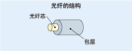
● Mode field diameter (MFD)
Technical parameters applicable to single mode fiber. Represents the diameter of the electric field distribution range (optical channel) of the transmission mode. Light usually passes through the fiber core range, but in the case of single-mode fibers, light can also leak into the cladding range, so it is not specified by the fiber core diameter but by the MFD. For this reason, the MFD is slightly larger than the fiber core diameter. The smaller the value, the higher the requirement for calibration accuracy. In addition, the greater the difference in the MFD between the connected fibers, the greater the wiring loss.
● Cladding diameter
The diameter of the circle closest to the surface of the cladding. The greater the difference in the diameter of the cladding between the connected fibers, the greater the connection loss.
● Optical cable cut-off wavelength
Technical parameters applicable to single mode fiber. If used at a wavelength less than this value, it is not a single mode. This value is determined by the construction of the fiber, such as the refractive index distribution and the size of the fiber core.
● Shielding grade
Shielding refers to the method of giving a certain elongation of the entire fiber in order to remove the defects of the glass and improve the reliability of the structure, so as to break the low-strength part in advance. The shielding grade indicates the value of this elongation. The greater the value, the higher the reliability of the fiber.
● Transmission loss
Represents the optical power reduction between two points when the fiber transmits light, expressed in the following formula.
Alpha =-(10/L) log (P2/P1)
L: Cable length
P: Power of incident light
P2: Output light power
The greater the value, the greater the reduction in optical power and, therefore, the shorter the transmission distance.
● Transmission frequency band
Technical parameters applicable to multi-mode fiber. Represents the frequency at which the size of the baseband transfer function is reduced to a specified value (6dB). In other words, it is the value that indicates the frequency up to which the signal can be transmitted without loss of authenticity. The higher the value, the more it can be transmitted at high frequency and large capacity.
● Zero dispersion wavelength
Technical parameters applicable to single mode fiber. Represents a wavelength with zero wavelength dispersion. If transmitted at a wavelength with a larger absolute value of wavelength dispersion, the dispersion will be larger and the distortion of the light pulse will also be larger. The optical fiber designed with zero dispersion wavelength near 1310nm is universal SM. The fiber designed near 1550nm is a dispersion-shifted fiber (DSF).
● Zero dispersion slope
Technical parameters applicable to single mode fiber. Represents the dispersion slope of the zero dispersion wavelength. If the zero dispersion slope is large, the absolute dispersion values of various wavelengths will generally increase.
Optical cable part of the relevant provisions
● Maximum allowable tension
The maximum tension that can be applied when laying the cable. However, this tension can not always be applied after laying, so it must be paid attention to.
● Minimum allowable bending radius
Minimum radius that the cable can bend. The minimum bending radius will be different during and after laying. In general, the minimum allowable bending radius is 20 times the radius of the optical fiber during laying and 10 times the radius of the optical fiber after laying.
● Applicable temperature range
Temperature environment in which optical fibers can be laid. Under normal circumstances, the standard is: if used outdoors, the applicable temperature range is -20~+60℃, if used indoors, the applicable temperature range is -10~+40℃.
● Waterproof characteristic rate
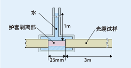
Under normal circumstances, the cable laid underground requires it to have waterproof characteristics. There are a variety of test methods, the company at room temperature for 24 consecutive hours to carry out the following test, generally in the cable will not have more than 3m degree of water as a standard, this standard varies according to the structure of the cable.
The relevant provisions of optical connectors
● Wiring loss
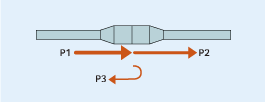
When connecting optical fibers to optical fibers, the loss of light from one optical fiber into the other optical fiber is expressed by the following formula.
α=-10log (P2/P1) [dB]
P1: optical power immediately at the front of the wiring position
P2: optical power reflected at the wiring position
The greater the value, the less light power is reflected and, therefore, the less noise.
● Reflection loss
It is the ratio of the incident optical power to the optical connector and the optical power reflected in the connection surface, expressed by the following formula.
α=-10log (P3/P1) [dB]
P1: optical power immediately at the front of the wiring position
P3: Optical power reflected at the wiring position
The greater the value, the less light power is reflected and, therefore, the less noise.
● Core grinding method
The grinding method of the core and the wiring characteristics of the connector are different.
Regulations for optical terminating/junction boxes and junction boxes
● Dustproof and waterproof features
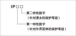
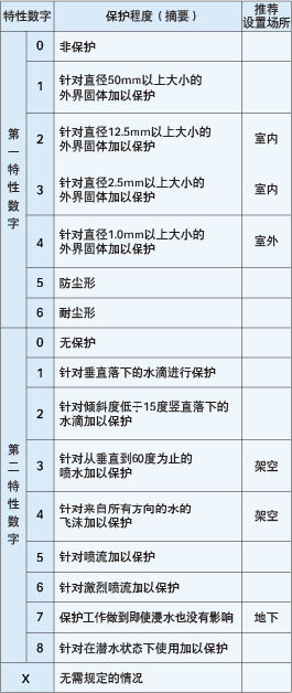
The optical terminal/junction box and junction box are required to be protected against general external solids and against water immersion (mainly outdoor). The classification of protection is expressed in the IP code specified in [JIS C 0920].
● Presentation method
IP54: Dust resistant and protected against water droplets.
IP3X: Protects against external solids with a diameter of more than 2.5mm. Save slightly for water protection.
IPX7: Omit the protection against external solids, and the protection work does not affect even if it is soaked in water.
● Presentation method
According to the transmission mode of light in the fiber, the fiber can be divided into single-mode fiber and multi-mode fiber.
Single-mode Fiber: The general fiber jumper is shown in yellow, and the connector and protective sleeve are blue; The transmission distance is long.
Multi-mode Fiber: The general fiber jumper is expressed in orange, and some are expressed in gray, and the connector and protective cover are beige or black; The transmission distance is short.
Multi-mode Fiber (MMF) has a thick core and can transmit multiple modes of light. However, the dispersion between modes is large, and the dispersion will gradually increase with the increase of transmission distance. The transmission distance of multimode fiber is also related to its transmission rate, core diameter and mode bandwidth.
Single Mode Fiber (SMF) has a thin core and can transmit only one mode of light. Therefore, the dispersion between modes is very small, which is suitable for remote communication.
Fiber diameter
The fiber diameter is generally expressed as the core diameter/cladding diameter, and the unit is μm. For example, 9/125μm indicates that the fiber core diameter is 9μm and the fiber cladding diameter is 125μm.
Optical fiber use notice
The transceiver wavelength of the optical modules at both ends of the optical fiber jumper must be the same, that is, the optical modules at both ends of the optical fiber must be of the same wavelength, and the simple way to distinguish is to have the same color of the optical modules. R> In general, short-wave optical modules use multi-mode fibers (orange fibers), and long-wave optical modules use single-mode fibers (yellow fibers) to ensure the accuracy of data transmission.
The optical fiber should not be excessively bent and looped in use, which will increase the attenuation of light during transmission.
After the optical fiber jumper is used, the optical fiber connector must be protected with a protective cover. Dust and oil will damage the coupling of the optical fiber.
Fiber optic connectors according to the different transmission media can be divided into common silicon-based fiber single-mode, multi-mode connectors, as well as other fiber optic connectors such as plastic and other transmission media; According to the structure of the connection head, it can be divided into: FC, SC, ST, LC, D4, DIN, MU, MT and so on. Among them, ST connectors are usually used for wiring equipment end, such as optical fiber distribution frame, optical fiber module, etc. SC and MT connectors are commonly used on the network device side. According to the end shape of the optical fiber, there are FC, PC (including SPC or UPC) and APC. According to the number of fiber cores, there are also single core and multi-core (such as MT-RJ).
FC round thread (most used on distribution frames)
ST clamp type round type
SC card square (most used on routers and switches)
MT-RJ square, one double fiber transceiver integrated
PC microsphere grinding and polishing
The APC is at an 8 degree Angle and is polished by micro spherical grinding
(PC, APC is the type of butt face)
Optical fiber used:
Single mode: L, wavelength 1310 Single mode long distance LH wavelength 1310,1550
Multimode :SM wavelength 850
SX/LH indicates that single-mode or multi-mode fibers can be used
Note In the labels for pigtail connectors, you can often see "FC/PC" and "SC/PC". The meanings are as follows
The part before/indicates the connector model of the pigtail
The "SC" joint is a standard square joint, made of engineering plastic, which has the advantages of high temperature resistance and not easy oxidation. Generally, an SC connector is used for the side optical interface of a transmission device. The LC connector has the same shape as the SC connector, but is smaller than the SC connector. The "FC" connector is a metal connector, generally used on the side of the optical fiber distribution frame (ODF), and the metal connector can be pluggable more times than the plastic.
Here is the reference diagram:

In the above figure, optical connectors are FC (commonly known as round head), SC (commonly known as square head), and LC.
FC type is divided into FC/FC and FC/PC(APC) type, the former FC is the abbreviation of Ferrule Connector, indicating that its external reinforcement is made of metal sleeve, fastening method is turnbuckle; The FC at the back indicates that the docking mode of the joint is plane docking, PC is the abbreviation of Physical Connection, indicating that the butt face is physical contact, that is, the end face is convex arch structure, APC and PC are similar, but a special grinding method is used, PC is a sphere, APC is a tilted 8-degree sphere, the index is better than PC. At present, FC/PC type is commonly used in telecommunication network, and FC/APC is mostly used in cable TV system. Generally written as FC or PC refers to the FC/PC optical connector.
SC shell adopts molding process, made of cast glass fiber plastic, rectangular shape; The plug sleeve (also known as the pin) is made of precision ceramic, the coupling sleeve is a metal slit sleeve structure, the structure size is the same as the FC type, and the end surface is treated by PC or APC type grinding; The fastening method is to use the plug and pull pin latch type, without rotating head. It is often used in data engineering. Generally, SC refers to SC/PC. Optical fiber connector developed by NTT Corporation of Japan. Its shell is rectangular, and the structural dimensions of the pins and coupling sleeves used are exactly the same as those of the FC type. The end face of the pin mostly adopts PC or APC grinding mode; The fastening method is to use the plug and pull pin latch type, without rotation. This kind of connector has the advantages of low price, easy insertion and removal operation, small fluctuation of intervention loss, high compressive strength and high installation density. ST and SC interfaces are two types of fiber optic connectors. For 10Base-F connections, the connector is usually ST, and for 100Base-FX, the connector is mostly SC. The core of the ST connector is exposed, and the core of the SC connector is inside the connector.
The LC fiber optic connector is made of modular jack (RJ) mechanism. The size of the pin and barrel used is half of the common SC, FC and other sizes. LC is commonly used on high-density optical interface boards of communication devices. The LC connector is developed by the famous Bell (Bell) Institute and is made of the easy-to-operate modular jack (RJ) latching mechanism. The size of the pin and sleeve used is half of the size used by ordinary SC, FC, etc., which is 1.25mm. This can improve the density of the optical fiber connector in the optical fiber distribution frame. At present, in terms of single-mode SFF, LC type connectors have actually occupied a dominant position, and the application of multi-mode is also growing rapidly.
Mt-rj (Mechanical Transfer Registered Jack) started from the MT connector developed by NTT, with the same latch mechanism as the RJ-45 LAN electrical connector, through the guide pin mounted on both sides of the small sleeve to the optical fiber, in order to facilitate the connection with the optical transceiver, The end fiber of the connector is a dual-core (0.75mm apart) arrangement design, which is the next generation of high-density fiber connectors mainly used for data transmission.
MU (Miniature unit Coupling) connector is the world's smallest single-core fiber optic connector developed by NTT based on the most used SC connector at present. The connector features a 1.25-mm diameter bushing and self-holding mechanism, which gives it the advantage of high-density installation. Using MU's l.25mm diameter bushing, NTT has developed the MU connector family. They have receptacle type connectors (MU-A series) for optical cable connections; Baseboard connectors with self-holding mechanism (MU-B series), simplified receptacles for connecting LD/PD modules to plugs (MU-SR series), etc. With the rapid development of optical fiber networks in the direction of larger bandwidth and larger capacity and the wide application of DWDM technology, the demand for MU connectors will also grow rapidly.
adapter

Above is the adapter corresponding to the various optical connectors, also known as flanges, used on the ODF for fiber connection.

The figure shows the FC/PC fiber jumper (informal name is double-ended pigtail), the English name is PATCH CORD, that is, the soft fiber with two optical connectors, used for the connection between the device and the ODF and the jump between the ODF. The optical jumper color is yellow, indicating a single-mode jumper.

The figure shows an MTRJ-SC fiber jumper. The color of the optical jumper is orange, indicating a multi-mode jumper.
In addition, there are PIGTAIL fibers for the end of the cable, English name PIGTAIL CORD, one end is fused with the cable, and one end is fixed on the ODF. In production, in order to facilitate testing, are produced as jumper, that is, both ends have optical fiber connectors, construction, cut from the middle, a jumper becomes two pigtails.
Cable pigtail
Features:
Adopt high quality ceramic dioxide core;
The outer diameter of the optical fiber can be selected from ¢0.9mm, ¢2.0mm, ¢3.0mm;
FC, SC, ST and other models to choose from;
Fiber length can be made according to user requirements;
Main technical indicators:
Insertion loss: ≤0.3db;
Return loss: PC≥40db,UPC≥50db,APC≥60db;
Change value of insertion loss in each experiment:
Interchangeability test: < 0.2db (arbitrary docking)
Vibration test: < 0.1db (5-50HZ, 1.5mm amplitude)
Tensile strength test: < 0.1db
High temperature test: < 0.2db (+85℃, after 100 hours of continuous)
Low temperature test: < 0.2db (-40℃, after 100 hours of continuous)
Temperature cycle test: < 0.2db (-40℃+85℃, after 5 cycles)
Temperature test: < 0.2db (-25℃+65℃, relative humidity 93%, after 100 hours)

coupler
Fiber Coupler (Coupler), also known as Splitter (Splitter), is the optical signal from a fiber to a number of optical fiber components, belongs to the field of optical passive components, in telecommunications networks, cable TV networks, user loop systems, regional networks will be applied to, and fiber optic connectors are the largest use of passive components. Fiber couplers can be divided into standard couplers (double branch, unit 1×2, which also divides the optical signal into two powers), star/tree couplers, and wavelength multiplexers (WDM, if the wavelength is high-density separation, that is, the wavelength spacing is narrow, it is DWDM), The production method is sintered (Fuse), micro-optics (Micro Optics), and optical waveguide (Wave Guide), and the sintering method accounts for the majority (about 90%). Many people make the mistake of using adapters as couplers.
